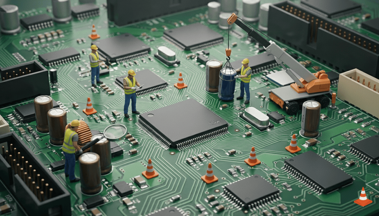
Introduction
Printed Circuit Boards (PCBs) are at the heart of almost every modern electronic device. From smartphones and laptops to TVs, routers, washing machines, and industrial controllers, PCBs make electronic systems compact, reliable, and repeatable.
When a device stops working, many people assume the entire unit is “dead.” In reality, a small PCB fault—like a broken trace, loose connector, or failed component—is often the real cause. Learning basic PCB repair can help you:
- Fix devices instead of replacing them
- Save money on repairs
- Understand how electronics actually work
- Build a foundation for electronics, mobile repair, or DIY projects
This guide is written for complete beginners to intermediate learners. You do not need an engineering background. We’ll start with core electronics concepts, then move step by step into PCB repair fundamentals, tools, common faults, and practical tips based on real-world repair experience.
What Is a PCB and Why It Matters
A Printed Circuit Board (PCB) is a flat board that mechanically supports and electrically connects electronic components using copper tracks, pads, and vias.
Instead of loose wires, PCBs provide:
- Stable connections
- Compact layout
- Reduced noise and interference
- Consistent manufacturing
In devices like an Android phone or iPhone, PCBs are often multilayer and highly compact, but the basic principles remain the same as simpler boards used in chargers, remotes, or power supplies.
Main Functions of a PCB
- Holds components in place
- Routes electrical signals correctly
- Distributes power safely
- Protects connections from movement and vibration
Understanding this structure is the first step toward effective repair.
Basic Electronics Concepts You Must Know
Before touching a soldering iron, it’s important to understand a few fundamental electronics concepts. These ideas explain why a PCB fails and how repairs work.
Voltage, Current, and Resistance (The Basics)
- Voltage (V): Electrical pressure that pushes electrons
- Current (A): Flow of electrons
- Resistance (Ω): Opposition to current flow
A simple rule used in repair is Ohm’s Law:
Voltage = Current × Resistance
You don’t need advanced math, but knowing this relationship helps when checking shorts, open circuits, or abnormal readings.
AC vs DC Power
- DC (Direct Current): Used by phones, laptops, routers, and most electronics
- AC (Alternating Current): Comes from wall sockets
Most PCB repairs involve low-voltage DC circuits, but power supply sections may still handle AC input—this area needs extra caution.
Series and Parallel Circuits
- Series: One broken connection can stop the entire circuit
- Parallel: Other paths may still work if one fails
This explains why sometimes part of a device works while another part doesn’t.
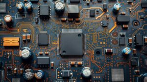
Common PCB Components and Their Roles
Understanding motherboard components helps you identify faults visually and electrically.
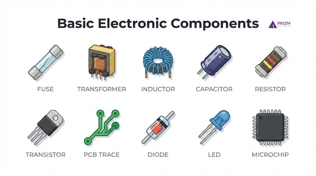
Resistors
- Control current flow
- Often marked with color bands or numbers
- Burnt resistors are common in power sections
Capacitors
- Store and release electrical energy
- Used for filtering and voltage smoothing
- Bulging or leaking capacitors are a frequent failure point
Diodes
- Allow current in one direction only
- Protect circuits from reverse polarity
LED (Light Emitting Diode)
- Emits light when current flows in one direction
- Used as status indicators (power, charging, activity)
- Requires correct polarity to function
- LED failure affects indication, not always circuit operation
Fuse
- Protects the PCB from overcurrent and short circuits
- Breaks the circuit when current exceeds safe limits
- Commonly placed near power input or charging circuits
- A blown fuse can cause the device to be completely dead
Inductor
- Stores energy in a magnetic field
- Helps smooth current and filter electrical noise
- Mainly used in power regulation circuits
- A faulty inductor may cause unstable voltage or overheating
Integrated Circuits (ICs)
- Perform logic, processing, or control
- Damage may not always be visible
Connectors and Ports
- USB, charging ports, ribbon connectors
- Very common failure points due to mechanical stress
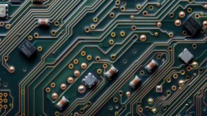
Understanding PCB Traces, Pads, and Layers
A PCB is more than components.
Copper Traces also called tracks
- Act like wires
- Can crack due to drops, heat, or corrosion
Pads
- Copper areas where components are soldered
- Pads can lift if overheated during repair
Single-Layer vs Multi-Layer PCBs
- Single-layer: Easier to repair (remotes, toys)
- Multi-layer: Used in smartphones and laptops; harder but still repairable with skill
Why PCBs Fail: Real-World Causes
From repair experience, most PCB failures come from a few repeat reasons:
- Liquid damage (water, tea, humidity)
- Physical stress (drops, bent connectors)
- Overheating
- Poor-quality charging adapters
- Aging components
In mobile phones, charging and power management sections are especially vulnerable.
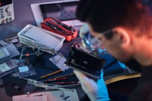
Essential Tools for Beginner PCB Repair
You don’t need an expensive lab to start motherboard repair.
Must-Have Tools
- Soldering iron (temperature controlled if possible)
- Multimeter (for voltage, continuity, resistance)
- Flux (improves solder flow)
- Solder wire (lead-free or leaded)
- Tweezers
- Magnifying glass or microscope
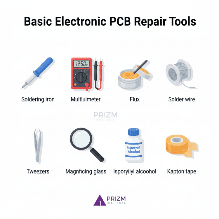
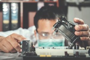
Nice-to-Have Tools
- Hot air rework station
- Isopropyl alcohol (IPA) for cleaning
- Kapton tape for heat protection
Start simple. Skill matters more than tools.
Safety Basics You Should Never Ignore
PCB repair is generally safe, but mistakes can be costly or dangerous.
- Always disconnect power
- Discharge capacitors before working
- Avoid touching live circuits
- Work in a well-ventilated area
- Wear eye protection when soldering
Power supply sections deserve extra caution.
Step-by-Step PCB Repair Approach for Beginners
Here’s a practical workflow used by technicians.
Step 1: Visual Inspection
Look for:
- Burn marks
- Corrosion
- Broken connectors
- Lifted pads
- Cracked components
Many faults are visible before any testing.
Step 2: Smell Test (Yes, Really)
Burnt components often have a distinct smell. This can quickly guide you to the faulty area.
Step 3: Continuity and Short Testing
Use a multimeter to:
- Check broken traces
- Detect short circuits
- Verify ground connections
This is critical in phone and charger PCBs.
Step 4: Component-Level Testing
- Check diodes for one-way conduction
- Measure resistors for correct values
- Look for shorted capacitors
Replace only what’s faulty.
Step 5: Repair and Reinforcement
- Rebuild broken traces with wire
- Replace damaged connectors
- Reinforce weak joints
Clean the area after soldering.
PCB Repair Decision Guide (Repair vs Replace)
| Situation | Repair Recommended? |
|---|---|
| Broken trace | ✅ Yes |
| Liquid damage, mild | ✅ Often |
| Burnt multilayer IC | ⚠️ Depends |
| Severe corrosion | ❌ Replace |
Common PCB Repair Mistakes Beginners Make
Avoiding these will save boards and confidence.
- Overheating pads and lifting them
- Using too much solder
- Skipping flux
- Replacing parts without diagnosis
- Applying power too early
Patience matters more than speed.
PCB Repair in Smartphones vs Other Devices
Smartphone PCB repair has unique challenges:
- Very small components
- Multi-layer boards
- Tight tolerances
- Heat-sensitive ICs
However, basic concepts remain identical whether you’re repairing a mobile device, router, or TV board.
Learning on simple boards first builds confidence for advanced repairs later.
Pros and Cons of Learning PCB Repair
Pros
- Saves money
- Builds technical skills
- Useful for phone and electronics repair
- Encourages sustainable repair culture
Cons
- Requires practice
- Initial mistakes are common
- Advanced boards need experience and tools
Balanced expectations help long-term success.
Practical Tips from Real Repair Experience
- Start with non-critical boards
- Practice soldering on scrap PCBs
- Label connectors before removal
- Take photos before disassembly
- Keep repair notes
Repair is a skill built through repetition.
Testing After Repair: How to Verify Your PCB Is Actually Fixed
Repairing a PCB does not end with soldering or replacing a component. Proper testing after repair is critical to confirm the fault is resolved and to avoid causing further damage when power is applied.
Skipping this step is one of the most common beginner mistakes.
1. Visual Re-Inspection (Do This First)
Before applying power, carefully inspect the repaired area:
- Look for solder bridges between nearby pads
- Check for cold solder joints (dull or cracked solder)
- Ensure no components are misaligned or reversed
- Confirm repaired traces are secure and insulated
A magnifying glass or microscope is extremely helpful here.
2. Continuity and Short-Circuit Testing
Use a multimeter in continuity or resistance mode.
- Verify repaired traces now show proper continuity
- Check power to ground for shorts (very important in smartphones)
- Compare readings with a known good section if possible
If a short still exists, do not power the board.
3. Component-Level Verification
Test the components you worked around:
- Diodes should conduct in only one direction
- Resistors should measure close to their rated value
- Capacitors should not show a dead short (unless designed that way)
This step confirms the repair did not introduce new faults.
4. Controlled Power-On Testing
When powering the PCB for the first time after repair:
- Use a current-limited power supply if available
- Start at a lower voltage
- Watch for sudden current spikes, heat, or smell
For mobile phones and other compact devices, this step helps prevent IC damage.
5. Functional Testing in Real Use
Finally, test the device under normal conditions:
- Check charging, power-on, display, or output behavior
- Gently move connectors to ensure stability
- Allow the device to run for some time to confirm reliability
A repair is successful only if the device works consistently, not just momentarily. This guide on electronics PCB motherboard repair course in India breaks down training duration, certification value, and employment options in the repair industry.
Common Myths About Motherboard Repair (And the Truth)
Many beginners struggle with motherboard repair because of misleading assumptions. Clearing these myths improves learning and prevents unnecessary damage.
Myth 1: “All PCB faults are visible to the eye”
Reality:
Many failures—such as shorted capacitors, internal IC faults, or hairline trace cracks—are not visible. Proper testing is just as important as visual inspection.
Myth 2: “More heat makes soldering better”
Reality:
Excessive heat can lift pads, damage components, and weaken PCB layers. Controlled temperature and good flux matter far more than brute heat.
Myth 3: “A multimeter alone can diagnose every PCB fault”
Reality:
A multimeter is essential, but it cannot detect everything. Some faults require logical analysis, comparison testing, or experience-based judgment.
Myth 4: “Once repaired, a PCB is as good as new”
Reality:
A properly repaired PCB can be reliable, but repaired areas are often mechanically weaker. Reinforcement and careful handling matter.
Myth 5: “PCB repair is only for experts”
Reality:
Basic PCB repair—like trace repair, connector replacement, and simple component fixes—is absolutely learnable for beginners with patience and practice.
Myth 6: “Replacing parts randomly will eventually fix the problem”
Reality:
Random replacement wastes time and can create new faults. Good repair is based on diagnosis first, replacement second.
This detailed breakdown of motherboard faults and repair methods helps you identify hardware issues early and avoid unnecessary system replacements.
Frequently Asked Questions (FAQs)
1. Can a beginner really repair a PCB?
Yes. Many common faults like broken traces or connectors are beginner-friendly with proper guidance.
2. Do I need an electronics degree to fix PCBs?
No. Practical knowledge and hands-on learning matter more than formal education.
3. Is PCB repair safe for smartphones?
Yes, if done carefully and with power disconnected. Charging sections need extra caution.
4. What is the most common PCB failure?
Liquid damage and mechanical stress are the most common causes.
5. Can damaged PCB traces be repaired?
Yes. Thin wires and proper soldering can restore broken traces.
6. Is PCB repair better than replacement?
For minor faults, repair is cheaper and environmentally better than replacement.
Before replacing your motherboard, read this complete step-by-step motherboard short circuit fixing guide to understand common causes, tools required, and repair techniques.
Conclusion
PCB repair may seem intimidating at first, but it is a practical and learnable skill. By understanding basic electronics concepts, recognizing common components, and following a structured repair approach, beginners can confidently fix many real-world electronic problems.
Whether you’re repairing a mobile phone, charger, or household device, the fundamentals stay the same. Start small, practice patiently, and focus on understanding why something failed—not just how to replace it.
With time and hands-on experience, PCB repair becomes less about fear and more about logic, observation, and skill.